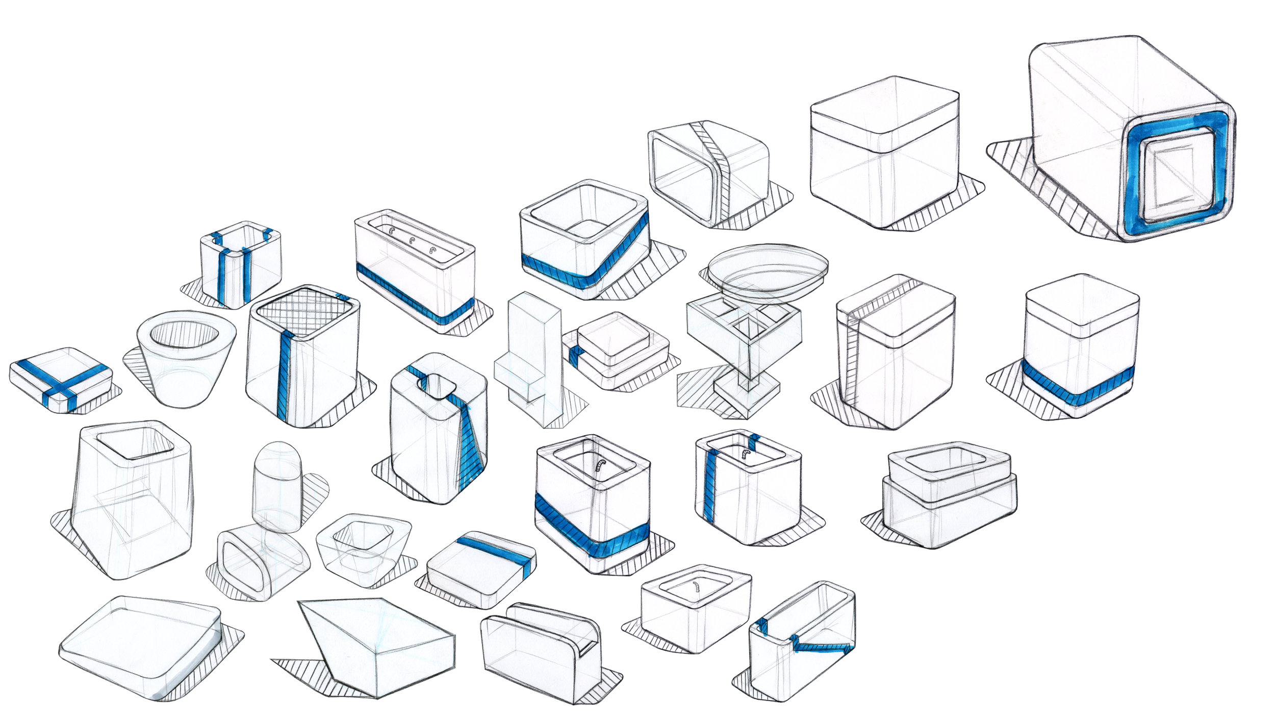
Shown above are a few of the ideation sketches relating to this idea.
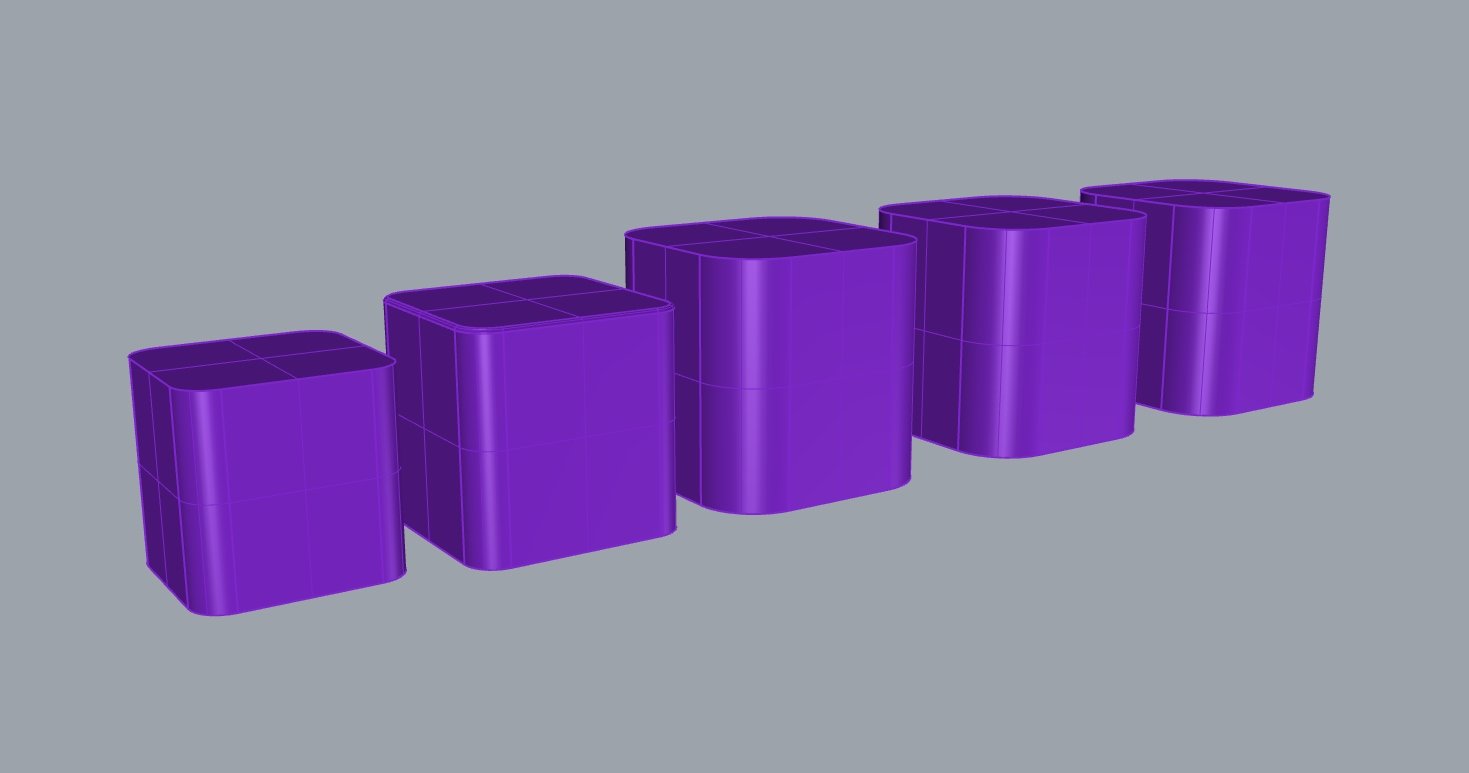
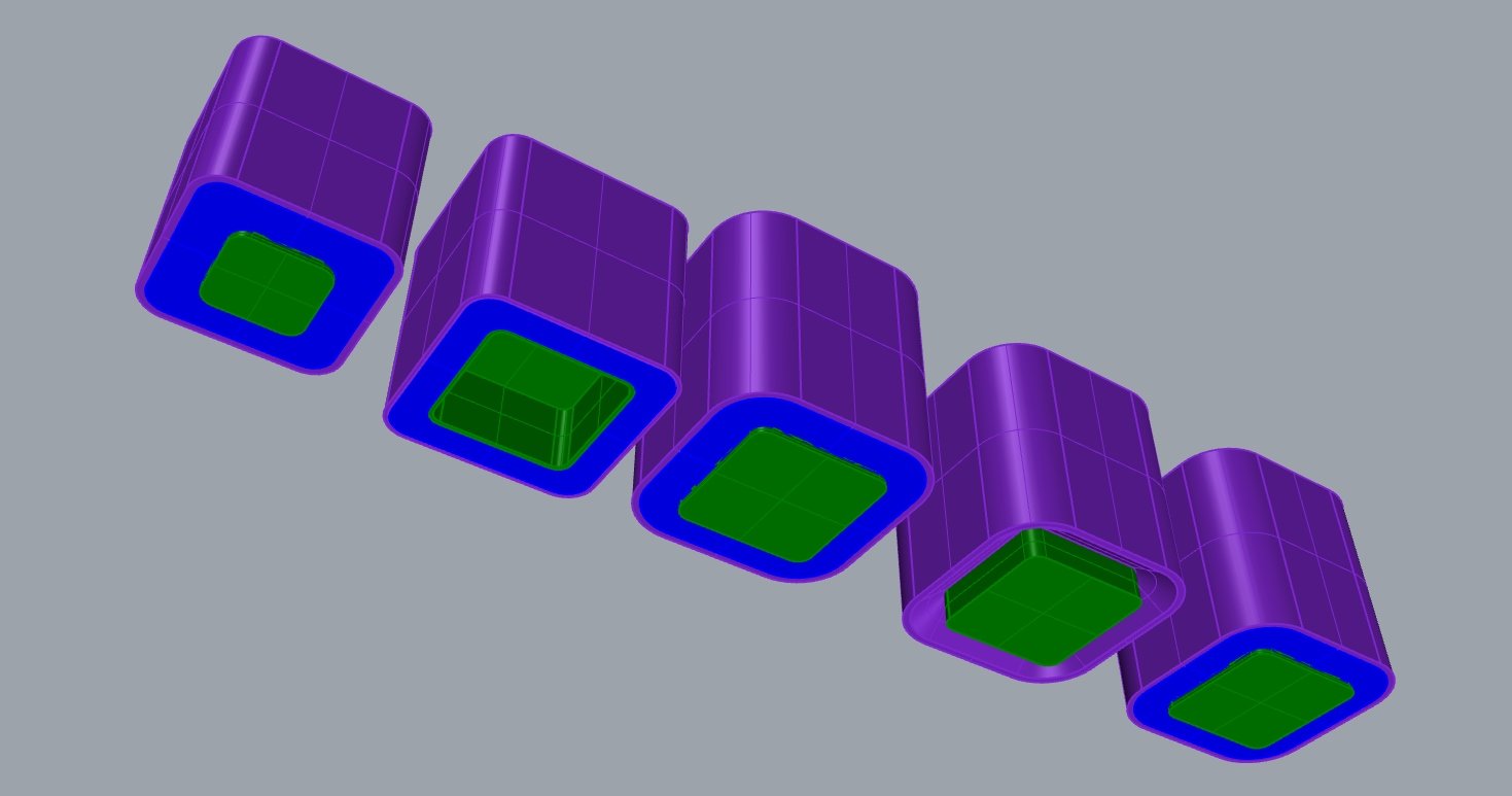
The following two images show the different iterations of modeling to hone in on the final shape and size of the Cube.
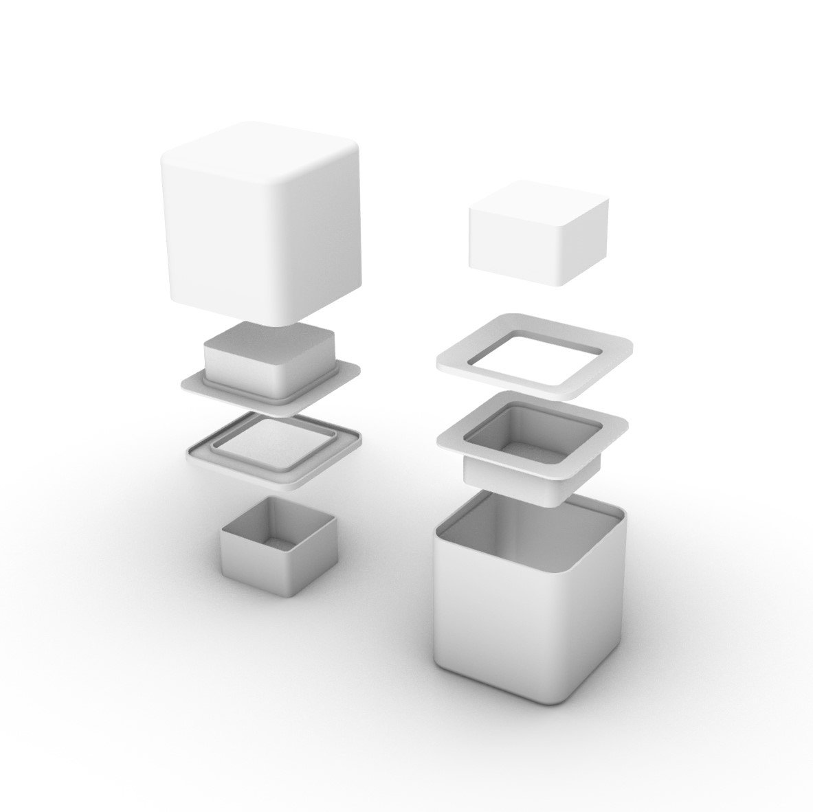
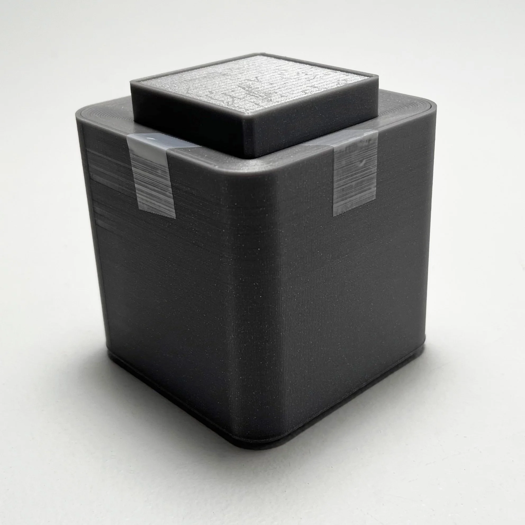
Shown is the final shape and size of the light. Brought in from the earlier iterations are a stacked shell design and new elements such as the angled square light, where the sketch only had a flat one.
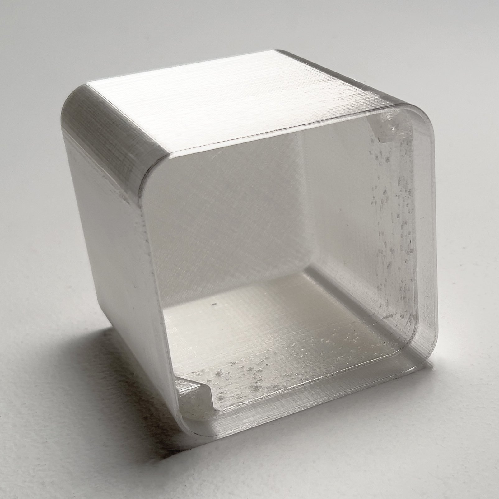
Next came a 3D quick 3D printed prototype of the shell to confirm that it was the right shape and size.

As with most of my projects, I planned on getting the Cube to as close to functional as possible. I picked out components and created an early protoboard mockup to confirm all parts worked.
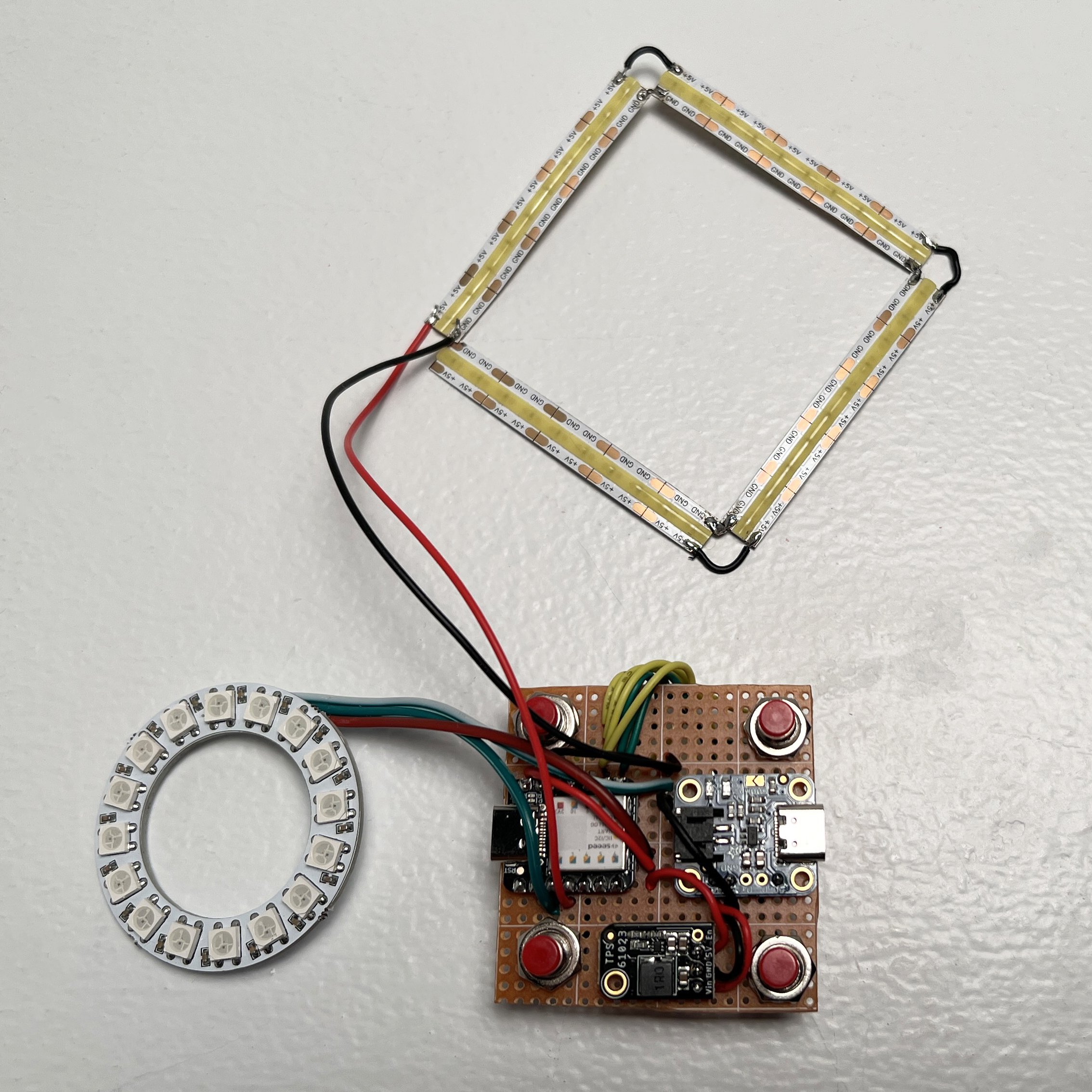
Here is the protoboard with both light assemblies. I delicately packaged this prototype and shipped it to a friend who majors in computer science. He worked with me to program the light.
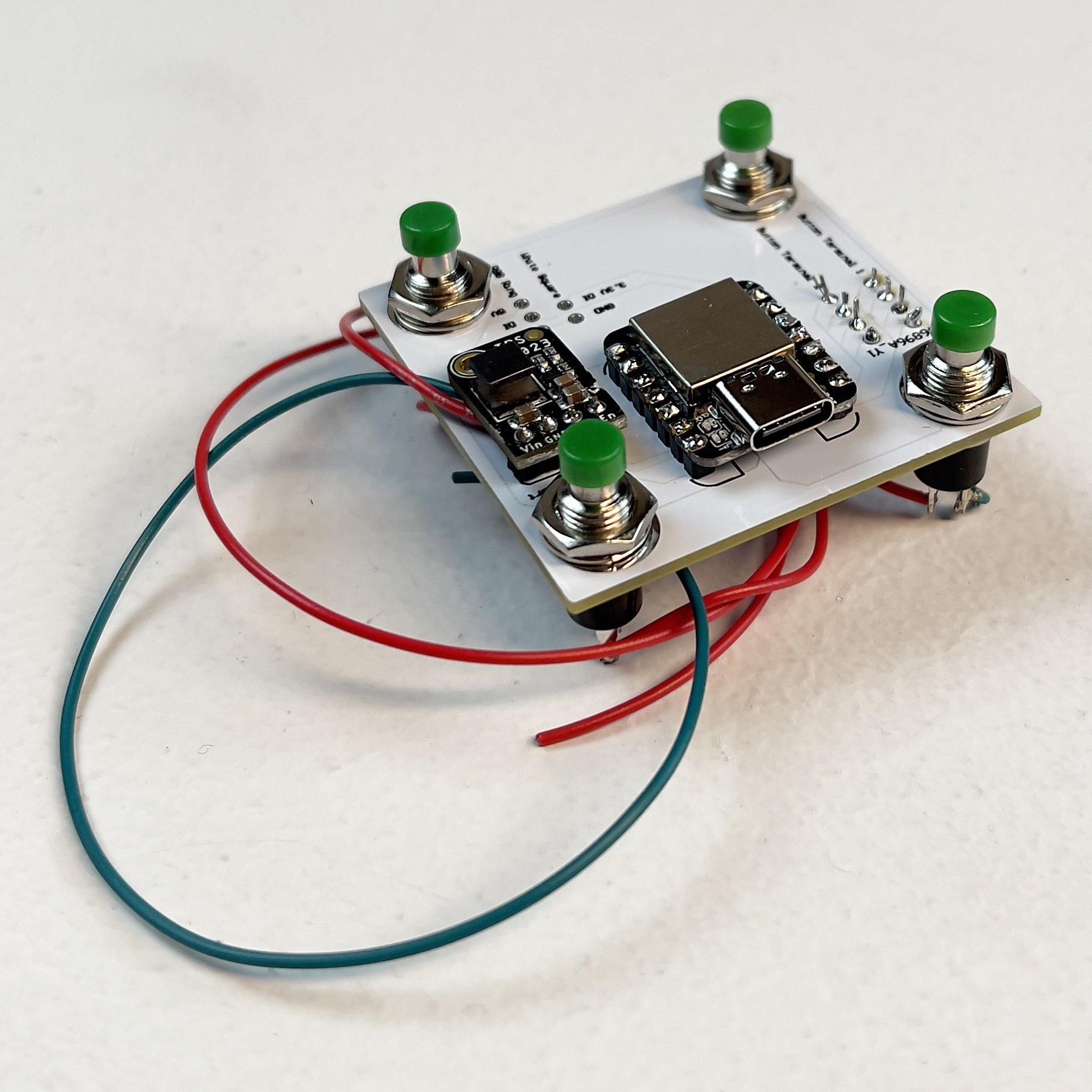
Between meetings with my friend to program the light, I continued with the design. I designed a PCB based on my prototype and had it manufactured in China.

With the internals designed and validated, I could proceed with production of the external components. I 3D printed a positive for the shell as well as a mold assembly to create a two part negative from silicone.

Shown is the full mold.

I cast a few resin shells from the mold. Though they completed, I was forced to label it a failure as I had not compensated for the resin expanding and contracting during the set and cure, leaving a rough ridge at the top. Were I to do it again, I would make the mold taller so I could simply sand the top down to size.
Though I learned from the mold, I lacked the time and funds to try again. I instead moved on to my contingency plan. I 3D printed the shell out of transparent PLA plastic and followed up by coating it in a layer of resin.

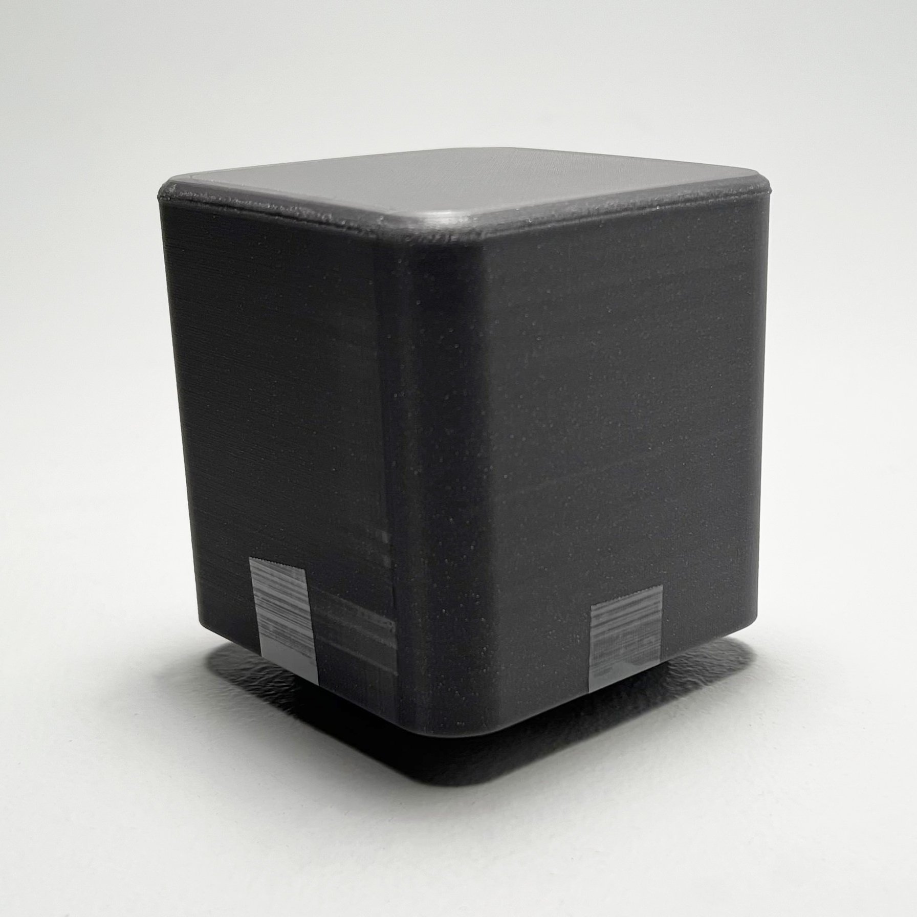
This method worked exceptionally well, only leaving the drip buildup at the bottom to be cleaned up. As seen in the final images, there are three models. the black one pictured here remained as is, and the white models were sanded with 400 grit sandpaper to achieve a frosted and diffused appearance.

With the shell a success, I began assembling the internal components. Pictured above is the light ring facing the top resin coated shell.
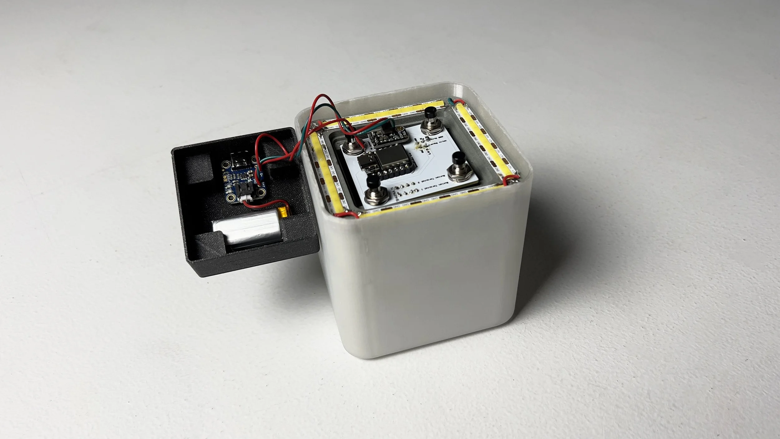
Pictured is the bottom facing assembly, consisting of the downward facing strip lights and the brain and battery.
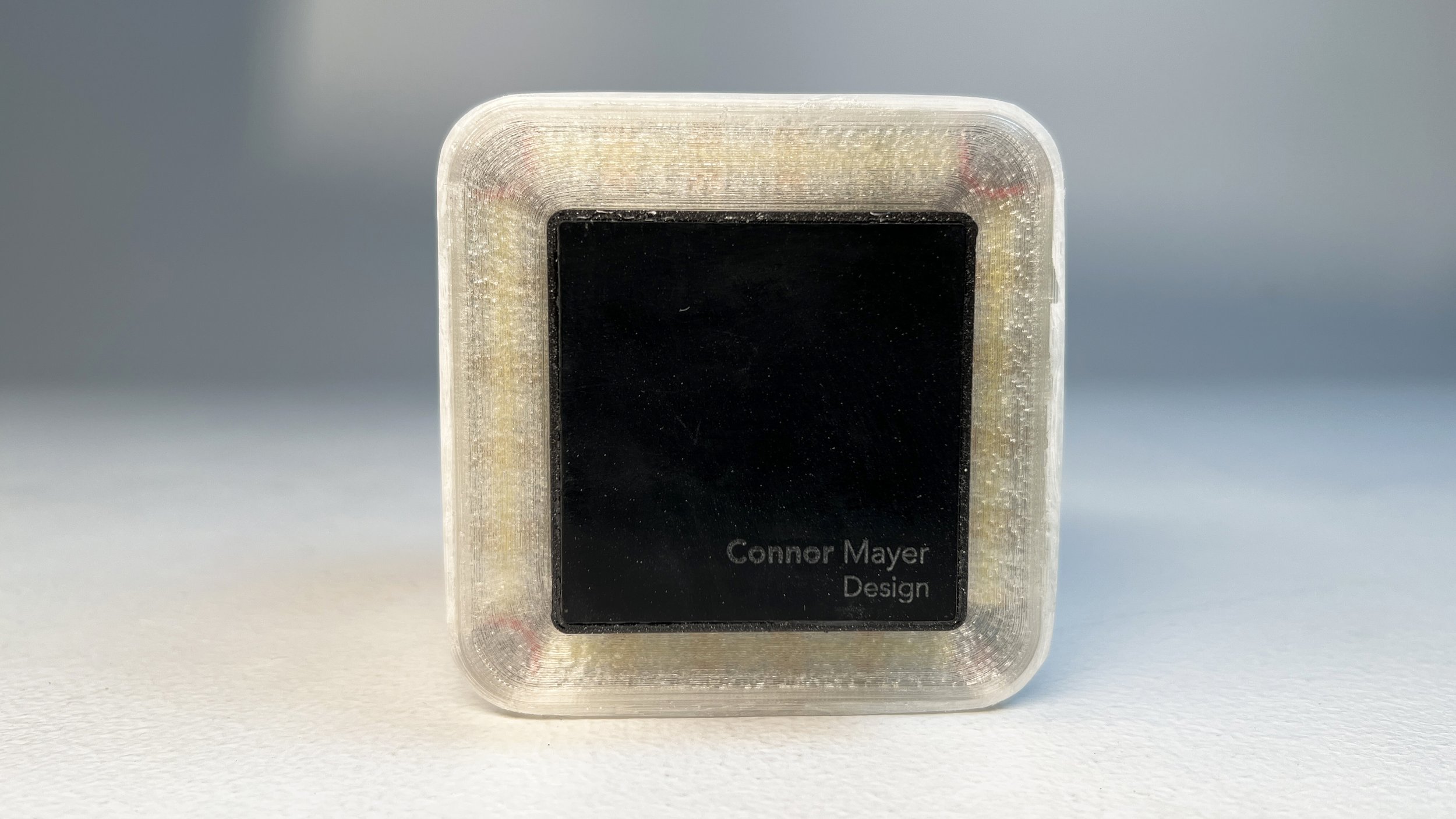
After assembling the interior, all that was left was to adhere the 3D printed light cover and the laser etched silicone foot. the layer lines, which are a natural result of the 3D printing process, serve to diffuse the light. The silicone foot is neatly recessed into the bottom of the light.